1. From the thermostat buttons, go to the "Wi-Fi mode" menu section by pressing the menu button until "APC" appears on the screen. Make sure that it is in the "AP" mode. If the screen is "CLI" (client), switch it to the "AP" mode.
2. On your computer, go to Wi-Fi settings and connect to the Wi-Fi network created by the thermostat. Its name will be in the format terneo sx_А68FDB (after "terneo" there should be the name of your model: sx, bx, or rzx). If a password is required for the connection, enter DSEXXXXXX, where XXXXXX represents the last six characters in the network name (for example: DSEА68FDB). The Android operating system may prompt you to confirm the connection to a Wi-Fi network that has no internet access. To proceed with the connection, press "Do not disconnect".
3. Open the browser and enter 192.168.0.1 in the address bar.
4. On the browser page of the thermostat interface, select your Wi-Fi network and enter its password. Click "Connect".
5. Please wait for a minute until the thermostat connects to your Wi-Fi network, and the indicator on the thermostat lights up blue.
6. Go to the Wi-Fi settings on your phone or computer and make sure you are already connected to your home Wi-Fi network.
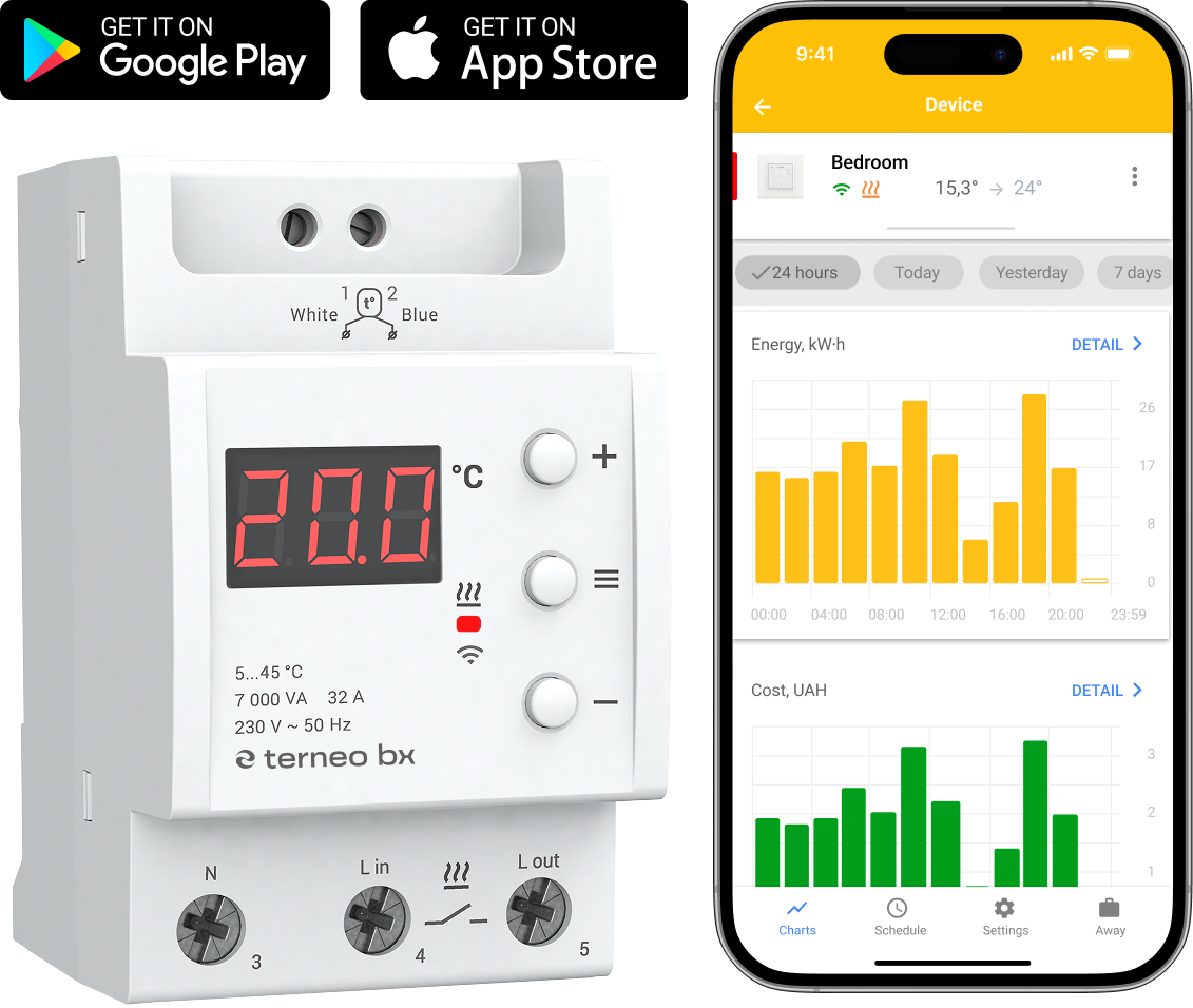
7. Go to my.terneo.ua and register using your Telegram, Apple ID, or Google account.
8. To add a thermostat, press "+ Add" → "Device" → set a name, for example, "Bedroom" → enter the PIN-code from the thermostat screen → press "Next" to add the device.
If you don't see the PIN-code on the
thermostat screen, press the "≡" 3 times until "Pin" appears on the screen. Then, press "+" or "–" to request the PIN-code.
Possible malfunctions:
— If instead of the PIN-code, the thermostat displays "iP", it indicates a lack of connection to the server. Check the internet connection on the router to which the thermostat is connected.
— If you cannot find the "Pin" and "iP" in the menu, it means there is no Wi-Fi connection. Repeat the connection process through the desktop application starting from step 1.